









Granite countertop fabrication converts a natural stone slab into accurately sized, finished components that can survive transport, installation, and years of service. The process combines digital measurement, slab inspection, layout, cutting, CNC machining, edge profiling, polishing, quality control, and material handling. Every stage affects yield, appearance, dimensional accuracy, and breakage risk.
For industrial fabricators, the challenge is not simply cutting granite. It is producing repeatable parts from a naturally variable material while controlling labor, tool wear, water, dust, cycle time, and rework. This guide explains the complete granite countertop manufacturing workflow for production managers, equipment buyers, CNC programmers, quality engineers, and fabrication teams.
What Is Granite Countertop Fabrication?
Granite countertop fabrication is the factory process of turning quarried and polished slabs into project-specific worktops, islands, vanity tops, backsplashes, and related components. Unlike standardized metal or plastic stock, every granite slab has unique color, veining, fissures, mineral structure, and defects. The production system must therefore combine accurate digital data with visual material planning.
A typical project begins with site dimensions or a digital template. The factory selects suitable slabs, positions each part in a nesting program, cuts the main geometry, machines sink and faucet openings, creates edge profiles, polishes exposed surfaces, inspects the finished parts, and packages them for installation.
Why Process Control Matters
Small errors accumulate. An incorrect template affects every downstream operation. Poor slab support can create a crack that appears only after polishing. Incorrect tool compensation can move a sink cutout or make a seam impossible to close. A controlled workflow prevents these problems by defining inputs, inspection gates, approved parameters, and responsibility at each stage.
Start with Accurate Measurement and Templating
Fabrication quality begins before the slab reaches the cutting table. The approved template must reflect cabinet position, wall shape, overhangs, finished edges, seams, appliance openings, backsplash dimensions, support locations, and installation clearances.
Digital templating systems capture points and convert them into CAD geometry. Physical templates can also be used when managed carefully. Regardless of method, the factory should verify scale, units, reference datums, part orientation, job revision, and any site assumptions.
Critical Information on the Fabrication Drawing
- Finished length, width, and thickness
- Wall and cabinet reference lines
- Seam positions and seam angles
- Sink, cooktop, faucet, and accessory openings
- Edge profile and polished-edge locations
- Corner radii and inside-corner requirements
- Overhangs, supports, and reinforcement details
- Backsplash height and end conditions
- Vein direction and visual-match instructions
A formal drawing approval step reduces disputes and prevents outdated files from reaching production. Revision control should remain visible in the nesting, CNC program, traveler, inspection report, and installation package.
Inspect and Photograph the Granite Slab
Inspect both surfaces and all edges before nesting. Record slab identification, bundle, dimensions, thickness, finish, and condition. Photograph the complete slab under consistent lighting so sales, engineering, and production can discuss the same visual information.
Map cracks, open fissures, resin repairs, pits, discoloration, weak inclusions, edge damage, and areas that cannot be used. Natural fissures may be acceptable, but they must be distinguished from structural cracks according to the company’s quality standard and the customer agreement.
Measure Actual Usable Area
Nominal slab dimensions do not equal usable area. Irregular boundaries, damaged corners, handling clearance, defects, and required factory-edge trimming reduce yield. Enter the true usable polygon into nesting software rather than assuming a perfect rectangle.
Check Thickness and Flatness
Measure thickness at multiple locations. Variation affects miter geometry, edge profiling, seam elevation, vacuum holding, and tool depth. A warped slab may require special support or may be unsuitable for a large component. Never force severe distortion flat with concentrated pressure.
Plan the Slab Layout and Vein Match
Layout determines both material yield and finished appearance. Parts must fit within usable regions while preserving edge clearances, kerf, tool access, defect exclusions, and grain direction. High utilization is valuable only when every nested component can be produced and installed successfully.
Use digital slab images when visual matching matters. Align seams, waterfalls, islands, and adjacent runs before releasing the nest. Keep orientation labels consistent from CAD through final packaging.
Balance Yield and Fabrication Risk
A nest that places a narrow sink rail across a fissure may save material but increase breakage probability. Similarly, positioning a finished edge close to a damaged slab boundary can create extra grinding or visible defects. The nesting decision should consider expected rework and scrap, not only percentage utilization.
For detailed methods on defect mapping and toolpath-aware layout, see stone slab nesting optimization for CNC cutting.
Select the Right Equipment for Each Operation
Modern granite countertop plants often combine several machines. The best production route depends on volume, product mix, part geometry, labor availability, quality requirements, and the existing factory layout.
| 設備 | Main operation | Strengths | Key process controls |
|---|---|---|---|
| Bridge saw | Slab sizing, straight cuts, miters | High straight-cut productivity and simple setup | Blade condition, feed, support, cooling, saw geometry |
| CNC machining center | Sink cutouts, faucet holes, curves, edge profiles | Programmable geometry and repeatability | Tool measurement, spindle runout, vacuum, toolpath |
| Abrasive waterjet | Complex contours, internal features, fragile shapes | Low mechanical load and narrow cutting kerf | Piercing, abrasive flow, pressure, standoff, taper |
| Edge polisher | Straight-edge grinding and polishing | Consistent finish at production volume | Head alignment, pressure, abrasive sequence, water |
| Manual workstations | Detail finishing, seam adjustment, inspection repair | Flexible for controlled secondary work | Templates, dust control, operator method, inspection |
A hybrid production cell frequently gives the best balance. The bridge saw handles fast primary cutting, CNC equipment produces openings and profiles, and manual stations complete only the details that do not justify a dedicated automated cycle. The guide to machines for kitchen countertop manufacturing provides a broader equipment overview.
Cut Granite Slabs on a Bridge Saw
Bridge-saw cutting establishes the main part geometry. Before loading, clean the table and confirm support condition. Position the slab according to the approved nest and verify orientation against the slab image and job traveler.
Choose a Granite-Rated Diamond Blade
Blade diameter, segment design, bond, diamond specification, core stiffness, and side clearance must match the granite family, machine power, spindle speed, and required feed. A blade designed for general masonry may not deliver acceptable countertop edge quality or tool life.
Clean the arbor and flange faces before installing the blade. Stone particles trapped between mounting surfaces create runout. Measure blade and spindle condition using the machine and tooling supplier’s procedure.
Control Feed and Spindle Speed
Start with the blade supplier’s parameter range and qualify it on representative material. Excessive feed raises cutting force and can produce chips or blade deflection. Feed that is too low may glaze the segments and create unnecessary heat. Monitor spindle load, cutting sound, water discharge, and edge condition.
Support the Slab and Offcut
Both sides of the kerf need stable support. An offcut that drops or rotates can break the exit edge, pinch the blade, or damage a narrow rail. Plan vacuum zones, stops, or other approved restraints so released sections cannot move into the toolpath.
Sequence Cuts for Stability
Complete cuts in an order that preserves support and avoids trapping the blade. Large cuts can release natural stress within granite. Do not leave a heavy component connected by a fragile bridge unless that bridge is part of a validated handling method.
Use Water for Cooling and Dust Control
Water cools diamond tooling, removes swarf, stabilizes cutting performance, and suppresses dust. Direct water to the active cutting zone on both sides of the blade or tool. High pump flow provides little benefit if the nozzles are blocked or aimed away from the contact point.
Inspect pumps, filters, hoses, settling systems, and nozzles routinely. Changes in water clarity, pressure, or discharge pattern can affect tool wear and finish. Stop production if coolant delivery fails.
Granite processing can generate respirable crystalline silica. Wet methods, local exhaust, enclosure, housekeeping, exposure monitoring, and respiratory protection should follow applicable regulations and qualified industrial-hygiene guidance. Compressed air and dry sweeping should not be used to disperse settled silica-containing dust.
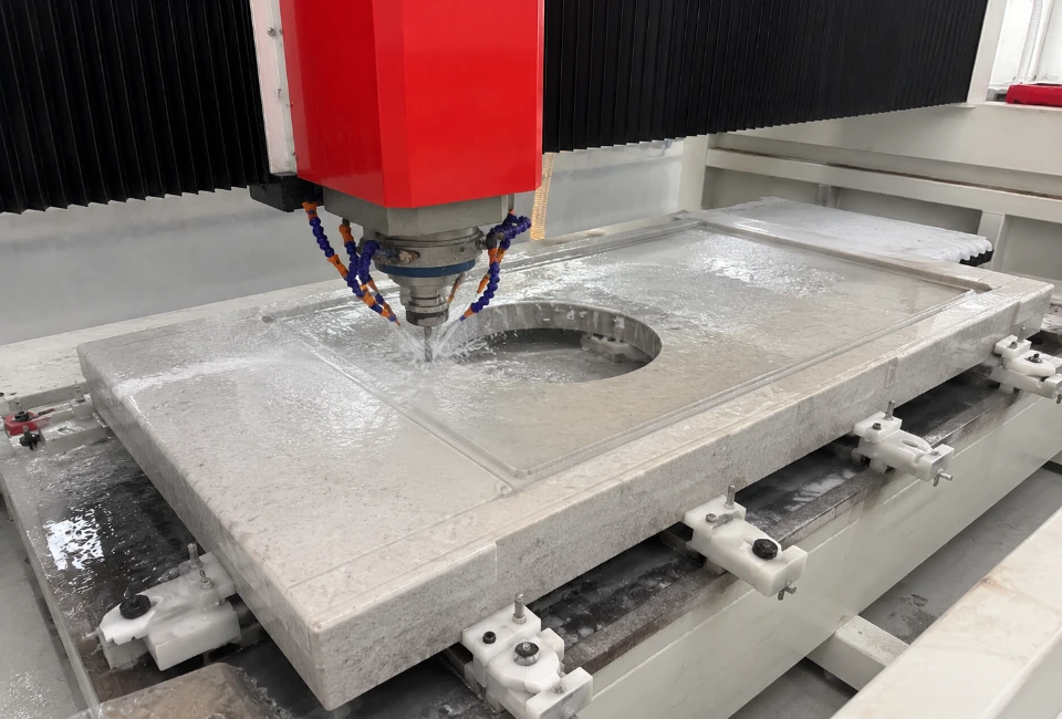
Machine Sink and Cooktop Cutouts
Cutouts create some of the highest-risk geometry in a countertop. They introduce internal corners, narrow rails, large removable slugs, and reduced part stiffness. Confirm the appliance or sink model, mounting method, clearance, corner radius, and reinforcement requirements before programming.
Round Internal Corners
Sharp inside corners concentrate stress. Use the specified radius and compatible diamond tooling. Core-drilled relief holes or continuous radiused toolpaths can reduce crack initiation when correctly programmed.
Plan Tool Entry
Enter from waste material whenever practical. CNC tools may use an approved ramp, helix, or predrilled entry rather than an uncontrolled plunge. Waterjet programs should pierce in waste and use a lead-in that keeps pierce damage away from the finished contour.
Control the Cutout Slug
The sink or cooktop slug must remain supported. If it drops, rotates, or binds, it can damage the tool and break surrounding rails. Use vacuum, temporary bridges, or another documented retention method. Remove bridges without shock loading the part.
Inspect Before Unloading
Check all internal corners for cracks, breakout, and incorrect radius. Confirm cutout dimensions and position before the component leaves the machine. Early detection prevents additional polishing and handling cost on a nonconforming part.
Produce Faucet Holes and Accessory Openings
Use a granite-rated diamond core drill with the correct diameter and adequate water delivery. A worn or glazed tool needs excessive pressure and can cause edge breakout. Verify hole center position, finished diameter, and minimum distance from cutouts and edges.
Support the underside when required and prevent the core from falling into a sensitive area. Program pecking or controlled feed according to tooling guidance. Inspect the hole for radial cracks and confirm that plumbing hardware has sufficient clearance.
Fabricate Mitered Granite Edges
Mitered edges create the appearance of thicker material but require accurate angle control and consistent remaining nose thickness. Calibrate the saw head or cutting axis before production. Check the miter along its full length because table twist or axis error may create variation from end to end.
Avoid cutting an unsupported knife edge unless the approved fabrication system calls for it. Leave a controlled allowance for finishing. Measure nose thickness at several points and protect the decorative surface from chipping during handling.
Dry-fit mating miter components before final bonding when the workflow allows. Verify angle, straightness, color alignment, and joint closure. Correcting a poorly matched miter at installation is slower and riskier than resolving it in the factory.
Profile and Polish Granite Edges
Edge finishing normally progresses from stock removal to profile generation, fine grinding, and polishing. Each tool should remove the marks left by the previous stage without creating waves, burns, or an incorrect profile.
Define the Tool Sequence
Use a documented sequence for each profile and granite family. Roughing tools establish geometry; intermediate abrasives refine scratches; polishing tools create the final gloss. Skipping stages overloads later tools and often produces uneven reflection.
Control Tool Pressure and Alignment
Automated polishers require aligned heads, consistent pressure, stable feed, sufficient water, and correctly dressed abrasives. Manual polishing requires templates, speed control, and inspection standards. Excess pressure can distort the profile or overheat the surface.
Match the Factory Surface
The edge gloss and color should visually match the slab face under defined lighting. Dark granite can show haze, swirl marks, and resin residue more clearly than lighter material. Inspect from more than one viewing angle.
For process selection and automation tradeoffs, see manual versus automated stone edge polishing.
Create Strong, Accurate Seams
Seams must satisfy dimensional, visual, structural, and installation requirements. Place them where cabinet support is adequate and where the components can be transported safely. Avoid unnecessary seams near weak cutout rails or locations that are difficult to clamp.
Machine seam edges straight and square to the approved joint design. Check elevation and thickness variation. Dry-fitting in the factory can reveal geometry problems, pattern mismatch, or edge damage before the parts reach the site.
Adhesive selection, color matching, clamping, and final finishing depend on the installation system. Fabrication drawings should state any factory-prepared reinforcement, slots, or hardware requirements.
Measure Granite Countertop Tolerances
Quality criteria should be numerical wherever possible. Define length, width, diagonal, squareness, straightness, cutout position, hole diameter, corner radius, miter angle, nose thickness, edge chips, surface defects, and polished-finish requirements.
| Inspection item | Typical method | Process issue detected |
|---|---|---|
| Overall dimensions | Calibrated tape, scale, or coordinate measurement | Template, compensation, or program error |
| Squareness and diagonals | Square and diagonal comparison | Axis calibration or layout error |
| Cutout position and radius | Template, caliper, or coordinate check | Wrong revision, toolpath, or tool diameter |
| Edge straightness | Reference straightedge and gap measurement | Blade deflection, axis error, or polishing waves |
| Miter angle and nose | Angle gauge and caliper | Saw-head calibration or table-flatness error |
| Gloss and appearance | Controlled visual inspection or gloss meter | Incomplete abrasive sequence or inconsistent pressure |
The article on stone cutting tolerances and quality control explains how to build inspection plans, measurement systems, and process-capability records.
Prevent Common Granite Fabrication Defects
Chipped Cut Edges
Inspect blade sharpness, feed, runout, support, water delivery, and exit conditions. Record whether chipping occurs on the top, bottom, entry, exit, or one side of the kerf; location helps identify the cause.
Cracks Around Sink Openings
Review corner radius, cutout sequence, slug control, slab defects, rail width, handling, and storage. Preserve failed parts long enough to identify the crack origin rather than immediately grinding away evidence.
Burned or Hazy Edges
Check abrasive sequence, tool glazing, pressure, speed, and water. A later polishing stage cannot always remove deep heat damage or an incorrect profile created during roughing.
Inaccurate Parts
Verify drawing revision, unit system, tool diameter, compensation, machine calibration, and first-off approval. Separate programming error from mechanical error before changing the process.
Broken Parts During Handling
Review lifting points, suction condition, rack design, narrow rails, unsupported overhangs, and worker coordination. A correctly machined part can still fail if twisted during unloading.
See the guide to common stone cutting problems and their solutions for additional diagnostic methods.
Handle and Store Finished Components
Use lifting frames, clamps, or suction equipment rated for the component. Inspect pads and vacuum circuits before every lift. Position lifting points on sound, clean surfaces and avoid unsupported cutout regions.
Move long countertops in the orientation specified by the handling plan. Do not twist components between supports. Parts with large openings or narrow rails may require temporary reinforcement for transport.
Store finished pieces on padded A-frames with restraints. Separate polished edges and miters from adjacent components. Labels should show project, part number, orientation, room, seam position, and any special installation note.
Organize the Factory for Efficient Material Flow
Machine cycle time is only one part of factory throughput. Slab retrieval, inspection, loading, program preparation, unloading, polishing, inspection, packaging, and movement between workstations can create longer delays than cutting.
Design the flow to minimize repeated lifting and crossing traffic. Separate raw slabs, work in process, rejected material, finished components, remnants, tooling, and packaging. Use clear staging locations and production status labels.
Track queue time as well as processing time. A fast CNC machine adds limited value if parts wait hours for unloading or inspection. Production data should identify the true constraint before the factory invests in additional equipment.
Use Production Data to Improve the Process
Record material yield, cutting time, CNC time, polishing hours, tool consumption, rework, breakage, and final inspection results by job and material family. Compare estimates with actual results.
Tool-life records should include granite family, operation, feed, speed, coolant condition, and failure mode. Replacing tools only after visible quality loss may create scrap; replacing them too early increases cost. Data supports a practical replacement interval.
When defects rise, change one controlled variable at a time. Simultaneous adjustments to tool, feed, water, support, and program prevent the team from learning which change solved the problem.
How to Evaluate Granite Fabrication Equipment
Equipment evaluation should use representative slabs and actual countertop features. A useful trial includes straight cuts, sink openings, faucet holes, internal radii, miters, edge profiles, and the handling of large finished parts.
Measure dimensional accuracy, edge condition, cycle time, tool wear, programming effort, changeover time, operator workload, water demand, maintenance access, and cleanup requirements. Ask how the system handles job revisions, slab images, tool measurement, vacuum zones, and production reporting.
Consider the full cost of the production cell: machine, tooling, software, water treatment, dust control, loading equipment, foundations, utilities, training, maintenance, and spare parts. Nominal cutting speed alone does not determine return on investment.
Granite Countertop Fabrication Checklist
Before production: confirm the approved drawing and revision; inspect and photograph the slab; map defects; verify thickness and usable area; approve the nest and vein match; confirm tooling, programs, support, water, and dust controls.
During production: monitor machine load, water delivery, vibration, edge condition, tool wear, vacuum holding, offcut movement, and cutout stability. Complete first-off inspection before continuing a batch.
After fabrication: inspect dimensions, seams, cutouts, corners, miters, edge profile, gloss, chips, and surface condition; record results; label parts; protect finished edges; reinforce fragile components; and package for safe installation.
常見問題
What machines are used for granite countertop fabrication?
Most industrial plants use a bridge saw for primary cutting, a CNC machining center for cutouts and profiles, edge-polishing equipment for finished edges, and material-handling systems for loading and unloading. Waterjet may be added for complex geometry.
What is the best blade for cutting granite countertops?
Use a diamond blade rated for granite and compatible with the saw’s diameter, power, spindle speed, flange, coolant system, and required feed. The best specification should be qualified on the actual granite families processed by the factory.
How are sink cutouts made in granite?
Sink openings are commonly produced with CNC finger bits, core drills, bridge-saw tooling, waterjet, or a validated combination. Programs should use rounded internal corners, controlled entry, stable slug retention, and immediate crack inspection.
How long does granite countertop fabrication take?
Lead time depends on project complexity, slab availability, layout approval, machine capacity, edge profiles, cutouts, finishing, inspection, and installation schedule. Processing time is only one component of total factory lead time.
How can a factory reduce granite breakage?
Inspect slabs, avoid defects during nesting, support parts continuously, use suitable tooling and cut sequences, round internal corners, secure cutout slugs, define lifting points, maintain suction equipment, and track failure origins.
Is waterjet useful for granite countertops?
Yes. Abrasive waterjet is useful for complex contours, internal features, and shapes where low mechanical cutting force is valuable. Piercing, taper, abrasive flow, water systems, and production speed still need careful control.
What quality checks are required before shipping?
Verify dimensions, diagonals, cutout positions, radii, seam edges, miter angle, nose thickness, edge profile, gloss, chips, cracks, surface condition, part labels, and packaging. Inspection should reference the approved drawing revision.
結論
Granite countertop fabrication is a coordinated production system, not a single cutting operation. Accurate templates, disciplined slab inspection, visual layout, correct machinery, qualified diamond tooling, stable support, controlled water and dust, careful cutout geometry, consistent polishing, and measurable inspection all determine the final result.
Factories that document recipes and connect quality data with tooling, machine condition, material family, and handling performance can reduce breakage while improving throughput. The result is a repeatable manufacturing process that protects both material value and installation quality.