









Stone slab handling and material flow automation covers every controlled movement between receiving, storage, inspection, cutting, machining, polishing, assembly, packing, and dispatch. In many stone factories, cutting equipment receives most of the investment attention while material movement remains dependent on forklifts, overhead cranes, manual carts, and operator judgment. This imbalance creates queues, damaged slabs, idle machines, ergonomic risk, and production schedules that appear efficient on paper but fail on the shop floor.
Granite, marble, quartzite, engineered quartz, porcelain, and sintered slabs combine high mass with large surface area and variable fragility. A slab may be strong while vertical yet vulnerable when carried flat or supported at too few points. Cut components introduce narrow rails, internal openings, polished edges, and matched surfaces that require different handling rules from raw material. Automation must therefore be designed around part condition, orientation, center of gravity, surface finish, and the next operation.
This technical guide explains how B2B stone processors can engineer safer and more predictable material flow. It covers process mapping, storage architecture, vacuum lifting, crane and robot integration, conveyors, transfer tables, work-in-process buffers, identification, takt time, control logic, maintenance, safety validation, and return-on-investment analysis. The objective is not to eliminate every manual action. It is to remove uncontrolled movement and ensure that the right slab or component arrives at the correct machine in the required condition and sequence.
Why Material Flow Determines Factory Capacity
A cutting machine produces only when material is positioned, identified, supported, and ready. If the operator waits for a crane, searches for a slab, clears a finished part, or resolves a storage conflict, spindle availability does not translate into output. In high-mix countertop and architectural production, handling can become the hidden constraint even when individual machines have sufficient nominal capacity.
Movement also affects quality. Fork contact can chip edges, suction cups can mark sensitive surfaces, unsupported cutouts can crack, and incorrect stacking can distort or scratch parts. Every transfer increases risk, particularly after cutting creates fragile geometry. A well-designed flow reduces transfer count and gives each movement a defined method.
Material-flow data improves scheduling. When arrival, queue, processing, and release times are captured, planners can distinguish machine cycle time from waiting time. This makes bottlenecks visible and prevents investment in another cutting machine when the actual constraint is loading, unloading, inspection, or internal transport.
Map the Current State Before Choosing Automation
Start with a physical flow map showing receiving points, slab racks, inspection areas, cranes, aisles, machines, buffers, polishing stations, packing zones, and waste routes. Trace representative jobs from unloading to shipment. Record distance, transfer count, orientation changes, waiting time, crew size, and equipment used.
Create separate maps for full slabs, remnants, cut components, finished assemblies, and rejected parts. Their routes and support requirements differ. Note every point where an operator must identify material, confirm a drawing, change a lifting device, or wait for shared equipment.
Use time observations rather than estimates. A transfer that takes five minutes in isolation may consume twenty minutes when crane availability, rack access, paperwork, and aisle congestion are included. Capture peak conditions and shift changes as well as normal production.
Define Handling Requirements by Material State
Raw Full Slabs
Full slabs normally arrive vertically on A-frames or in bundles. Handling equipment must accommodate maximum dimensions, thickness, mass, surface texture, and packaging. Natural slabs may contain hidden fissures, while large-format sintered sheets can be thin and sensitive to bending. Receiving inspection should identify damaged edges and structural risks before the first lift.
Nested Slabs Before Cutting
Once a slab is assigned to a job, orientation matters. The digital image, face side, vein direction, and programmed origin must match the physical setup. Identification should remain visible during staging so the machine operator does not rely on memory or handwritten notes.
Parts with Internal Cutouts
Sink and appliance openings reduce stiffness. Moving the part flat may be safer than lifting it vertically, but support must remain close to fragile rails. Vacuum-cup placement should avoid holes and weak regions. Handling instructions can be generated from the part geometry and displayed with the job traveler.
Polished and Finished Components
Finished surfaces require clean contact materials and controlled spacing. Edge profiles, miters, and laminated sections create local vulnerabilities. Racks should prevent part-to-part rubbing and allow retrieval without moving unrelated pieces.
Storage Architecture for Predictable Retrieval
Storage is part of the flow system, not unused floor space. Random placement increases search time and encourages extra crane moves. Define locations by material family, thickness, finish, batch, slab size, and production status. The physical rack label and digital inventory location must agree.
Vertical A-frame storage is space-efficient and familiar, but access to a slab buried inside a bundle can require multiple moves. Single-slot or movable-rack systems improve selectivity at higher capital and floor-space cost. Automated slab warehouses provide dense storage and machine-directed retrieval but require disciplined identification and reliable controls.
Remnants need their own policy. Record true dimensions or contour, material, batch, finish, defects, date, and location. The principles described in stone slab nesting optimization are more valuable when reusable remnants can actually be found and delivered to the machine.
Vacuum Lifting System Engineering
Load Capacity and Safety Factor
Select lifting equipment for the maximum verified load, including attachments and dynamic effects. Rated capacity may depend on cup configuration, material orientation, vacuum level, surface condition, and applicable lifting standard. Never treat the largest number on a product label as universal capacity.
Suction-Cup Selection
Cup diameter, material, lip design, and layout affect sealing and load distribution. Smooth polished stone may seal easily, while textured, flamed, wet, dusty, or porous surfaces require different solutions. Multiple independently monitored vacuum circuits can provide redundancy for large or irregular loads.
Vacuum Generation and Monitoring
Pumps, ejectors, reservoirs, non-return valves, filters, gauges, and alarms form one safety system. The device should maintain the load through a defined power-loss condition and warn the operator before vacuum becomes unsafe. Filters and seals need inspection because slurry and dust degrade performance.
Cup Placement and Part Geometry
Place cups on sound, sufficiently large regions and distribute load around the center of gravity. Avoid cracks, resin-filled areas, labels, holes, narrow rails, and heavy surface contamination. For cut parts, lifting plans should account for the remaining geometry rather than using the raw slab center.
Cranes, Jib Arms, Manipulators, and Robots
| Handling Method | Best Use | Main Advantage | Key Limitation |
|---|---|---|---|
| Overhead bridge crane | Plant-wide slab transfer | Large coverage and high capacity | Shared resource can create queues |
| Jib crane | Dedicated machine loading zone | Fast local access | Limited radius and overlap |
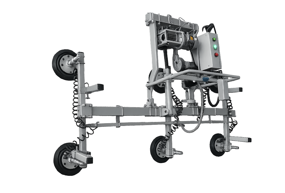
| Vacuum manipulator | Frequent controlled positioning | Low operator effort and fine movement | Requires suitable contact surface |
| Forklift with approved attachment | Receiving and long-distance movement | Flexible routing | Traffic, visibility, and edge-contact risks |
| Industrial robot | Repeatable loading and unloading | Programmable sequence and integration | Needs defined geometry, guarding, and reliable sensing |
Coverage areas should be designed to minimize handoffs. When one crane cannot reach both storage and machine, the transfer point needs defined support and control. Overlapping crane zones can improve continuity but also introduce collision risks that require operating rules or interlocks.
Robots are effective when part identification, orientation, pickup location, and destination are predictable. Vision and 3D sensing can accommodate variation, but fixtures and data quality remain important. Robot reach studies must include the load, gripper, wrist orientation, cable routing, and safe approach—not only the nominal tool-center envelope.
Conveyors and Transfer Tables
Roller conveyors, belt conveyors, powered carts, shuttle tables, and air-float tables can connect machines without repeated crane lifting. Equipment must support the part across fragile regions and prevent contact damage. Roller spacing should reflect the smallest or weakest component, not only the full slab.
Transfer direction matters. A ninety-degree change may require pop-up conveyors, turntables, or coordinated rollers. Each mechanism adds cycle time, maintenance, and control logic. The simplest route with the fewest orientation changes is usually the most reliable.
Water and slurry migrate with parts leaving wet processes. Conveyors need drainage, corrosion resistance, accessible cleaning, and sensors positioned away from persistent contamination. Accumulated fines can change roller height and scratch finished surfaces.
Design Work-in-Process Buffers
Zero inventory between every process sounds efficient but makes the entire line sensitive to small disturbances. A controlled buffer decouples machines with different cycle times and maintenance patterns. The buffer should have a defined capacity, location logic, maximum dwell time, and release rule.
Too much work in process hides problems and consumes floor space. Too little forces upstream machines to stop whenever downstream work pauses. Simulate typical product mixes and breakdown scenarios to determine buffer capacity. Separate fragile, matched, or urgent jobs where necessary.
Buffers also require physical support rules. Vertical racks may suit intact panels, while cut countertops with openings may need horizontal frames. Each position should preserve identification and allow access without moving several unrelated parts.
Synchronize Handling with Cutting and Machining
Machine cycle time is only one part of station takt. Include approach, pickup, transport, alignment, clamping, verification, unloading, inspection, and departure. A machine with a ten-minute cutting cycle and an eight-minute exchange process cannot achieve a ten-minute station takt.
Quick-change tables, dual work zones, pallet systems, or parallel unloading can reduce exchange time. The correct solution depends on whether the constraint is crane availability, operator travel, suction setup, part inspection, or machine access.
For factories comparing different cutting cells, waterjet cutting and CNC machining provides useful process context. Handling requirements should be included in equipment evaluation because the machine footprint alone does not represent the full operating cell.
Identification and Digital Traceability
Every slab, remnant, component, rack position, cart, and buffer location should have a controlled identity. Barcodes or QR codes reduce manual entry, while RFID can support automated detection where the environment and tag placement are suitable. Labels must tolerate water, slurry, abrasion, and cleaning.
The production system should confirm material identity before loading. It should also record movement time, source, destination, operator or automated device, and status. When a matched set is split across stations, the system must preserve the relationship.
Digital traceability connects physical flow with the tolerance controls described in stone cutting tolerances and quality control. If a part is damaged or dimensionally incorrect, movement history helps distinguish machining failure from handling damage.
Control Logic for Automated Material Flow
Job Dispatch
The control system should release material based on machine readiness, priority, tool availability, downstream capacity, and matched-set constraints. First-in-first-out is useful for some queues but inappropriate when material batch, cure time, or project sequence matters.
Handshake Signals
Upstream and downstream equipment need explicit states such as ready to receive, load present, identity confirmed, safe to transfer, cycle complete, and fault. Ambiguous signals create stopped lines or unsafe movement. Define recovery after lost communication and manual intervention.
Collision and Zone Management
Cranes, carts, robots, and operators may share space. Zone controls can prevent two devices from entering the same region. Physical guarding, scanners, interlocks, speed limits, warning devices, and traffic rules should be selected through formal risk assessment.
Exception Handling
Automation must manage missing labels, incorrect orientation, vacuum loss, damaged parts, blocked routes, full buffers, and machine downtime. Provide safe manual recovery with clear authority and logging. A system that works only under ideal conditions will quickly be bypassed.
Protect Material Quality During Transfer
Define acceptable contact materials for polished, honed, textured, and coated surfaces. Keep cups, rollers, and pads clean. Small particles trapped between a support and finished surface can create scratches across an entire batch.
Acceleration and braking should be controlled. Sudden movement causes swinging loads and increases forces on suction devices. Robot paths should minimize unnecessary reorientation and maintain a safe load attitude. Large thin sheets may need frames or spreader beams to limit bending.
Inspect critical parts after high-risk transfers. Damage classification should include chips, cracks, scratches, edge impact, contamination, deformation, and loss of match orientation. Trend failures by device and transfer point.
Safety Engineering and Validation
Material handling involves suspended loads, crush zones, stored vacuum energy, moving vehicles, and large brittle sheets. Conduct a task- and machine-specific risk assessment covering normal operation, setup, cleaning, maintenance, fault recovery, and power loss.
Keep personnel out of fall zones and never rely on vacuum alone where secondary support is required by the application or standard. Define inspection intervals for lifting devices, cups, hoses, valves, hooks, slings, structural attachments, and alarms. Remove damaged equipment from service immediately.
Training should include load assessment, cup placement, pre-use checks, communication, travel route, exclusion zones, emergency response, and limitations for porous or textured stone. Automation changes the hazards but does not remove the need for trained supervision.
Measure Material Flow Performance
Track transfer time, machine wait-for-material time, queue duration, handling labor, moves per part, distance traveled, damage rate, near misses, buffer occupancy, retrieval accuracy, and on-time delivery to each station. Segment data by product type and material state.
Overall equipment effectiveness can mislead when handling loss is recorded as planned downtime. Maintain a separate reason code for material unavailable, crane unavailable, identification error, buffer full, and unloading delay. This shows whether improvement belongs in the machine, logistics, planning, or quality system.
A spaghetti diagram visualizes distance and crossing routes, while a value-stream map reveals waiting and queue time. Use both because short physical movement can still include long information delays.
Maintenance Requirements for Handling Automation
Daily checks should cover suction cups, hoses, filters, vacuum alarms, hooks, controls, sensors, rails, wheels, rollers, emergency stops, and visible structural damage. Clean contact surfaces and drainage paths before deposits affect grip or level.
Periodic maintenance should inspect bearings, gearboxes, brakes, electrical cabinets, cable systems, robot calibration, crane alignment, fasteners, and safety devices. Verify load-monitoring and vacuum-switch settings with appropriate test equipment.
Plan access before installation. A motor or valve positioned above an occupied production line may require extensive shutdown for routine service. Provide platforms, isolation points, lifting access, and spare-part strategy for critical components.
Common Automation Mistakes
Automating an inefficient layout: Fast equipment cannot compensate for unnecessary distance and repeated orientation changes. Simplify the route first.
Selecting by maximum load only: Surface texture, geometry, center of gravity, acceleration, and redundancy also determine handling safety.
Ignoring exceptions: Missing labels and damaged parts force uncontrolled manual work. Design recovery paths before commissioning.
Eliminating every buffer: Small disruptions stop the entire line. Use controlled buffers based on variability.
Using one support method for every part: Raw slabs, cutouts, narrow rails, and finished assemblies require different contact and orientation rules.
Separating logistics data from production data: The scheduler cannot make reliable decisions without real location and readiness information.
Economic Evaluation
Capital cost includes cranes, manipulators, vacuum lifters, conveyors, carts, robots, racks, guarding, controls, software integration, civil work, utilities, and commissioning. Operating cost includes power, maintenance, inspection, consumables, training, and spare parts.
Benefits include reduced handling labor, lower damage and recut rates, less machine waiting, faster retrieval, improved floor-space use, safer work, and more predictable delivery. Evaluate throughput at the whole-line level. Saving one minute at a non-bottleneck station may have little financial value.
Run scenarios for product mix, shifts, downtime, and expansion. A phased design can begin with identification and layout improvements, then add dedicated lifting, powered transfer, buffers, and automated dispatch as volume justifies each step.
Implementation Roadmap
First, map current movement and collect time data. Second, classify loads and risks. Third, redesign storage, aisles, and machine adjacency. Fourth, establish identification and location control. Fifth, select handling devices using verified loads and surfaces. Sixth, simulate capacity and exceptions. Seventh, install guarding and controls. Finally, commission with representative slabs and parts.
Acceptance testing should cover maximum load, minimum part, porous and textured surfaces, fragile cutouts, power loss, vacuum leakage, sensor failure, full buffers, blocked routes, manual recovery, and emergency stopping. Confirm cycle time without relaxing safety controls.
FAQ: Stone Slab Handling Automation
When should a stone factory automate slab handling?
Automation becomes attractive when handling limits machine utilization, labor availability, safety, quality, or scheduling. Begin with measured waiting, transfer, and damage data rather than choosing a system solely from production volume.
Can vacuum lifters handle textured stone?
Some systems can, but capacity depends on cup design, surface porosity, texture, contamination, vacuum reserve, and redundancy. The exact material should be tested under controlled conditions.
Are robots suitable for high-mix countertop production?
Yes when reliable CAD data, part identification, pickup geometry, sensing, and exception handling are available. Flexible grippers and vision improve adaptability, but integration quality determines performance.
Should slabs be transported vertically or horizontally?
The safest orientation depends on material, thickness, geometry, support, route, and equipment. Full slabs are commonly moved vertically, while fragile cut parts may require distributed horizontal support.
How large should a work-in-process buffer be?
Capacity should reflect cycle-time variation, downtime, product mix, changeovers, and recovery targets. Simulation and real production data provide a stronger basis than a fixed rule.
What data is needed for automated routing?
The system needs material identity, location, dimensions, mass, orientation, job priority, required process sequence, machine status, buffer capacity, and handling constraints.
How can handling damage be reduced?
Reduce transfer count, use correct support, maintain clean contact surfaces, control speed, protect finished edges, preserve identification, and analyze damage by device and location.
Technical Audit Checklist
Before approving a material-flow system, verify: load families are documented; routes and transfer counts are mapped; lifting capacity includes operating conditions; suction devices are tested on actual surfaces; fragile geometry has defined support; storage locations are traceable; buffers have release rules; machines exchange clear handshake signals; fault recovery is safe; and inspection and maintenance responsibilities are assigned.
For a new line, conduct a factory acceptance test with representative full slabs, remnants, sink cutouts, narrow rails, polished components, and matched assemblies. Measure end-to-end flow, not only the speed of one robot or conveyor.
Conclusion
Stone slab handling and material flow automation connects storage, production, quality, safety, and scheduling. Its value comes from reducing uncontrolled transfers and machine waiting while protecting fragile, high-value material throughout the process.
The strongest implementation begins with a simplified layout and accurate load data, then applies the appropriate combination of racks, vacuum lifting, cranes, conveyors, buffers, robots, identification, and controls. By measuring whole-line performance and planning for exceptions, B2B stone fabricators can increase usable capacity without sacrificing part quality or operational safety.